- Published on
Découverte plateforme RISC V avec le GD32VF103 - Partie 4
- Authors
- Name
- Anthony Rabine
Dans ce nouvel article sur le processeur GD32 RISC-V, nous allons mettre en oeuvre un écran LCD !
Présentation de l'écran
L'écran que nous allons utiliser est un classique TFT à base de contrôleur ILI9341. On en trouve sur toutes les boutiques web. Le notre se présente de la sorte :
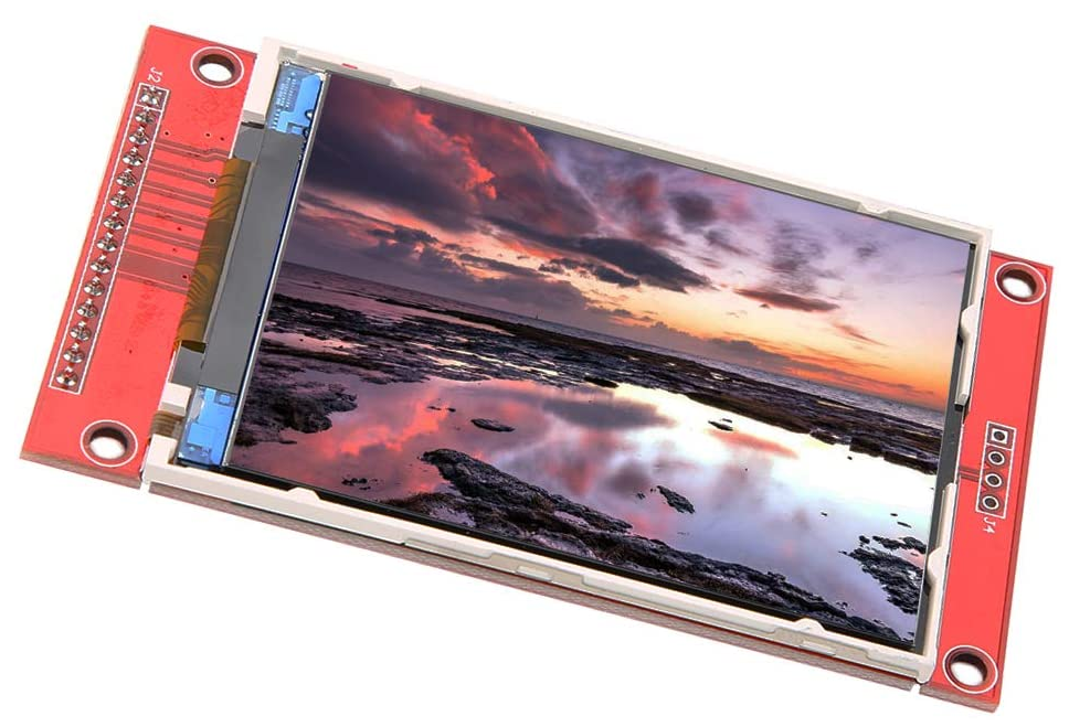
Selon la version, il peut comprendre une zone tactile que nous n'allons pas utiliser ici. Il contient néanmoins un slot pour cartes SD qui peut s'avérer intéressant si la carte de votre microcontrôleur n'en possède pas déjà.
Connexion au Longan Nano
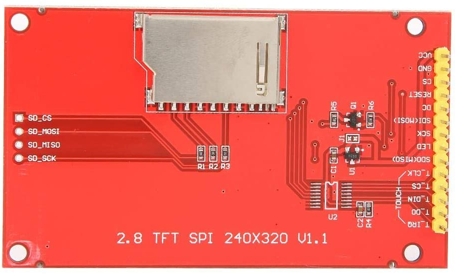
Le brochage qui nous intéresse est le suivant. Nous allons utiliser le SPI0 du Longan.
| LCD | Longan | Description |
|---|---|---|
| VCC | 3.3 | Alimentation + |
| Gnd | 3.3 | Alimentation (masse) |
| CS | PA4 | Chip Select (NSS0) |
| Reset | PA3 | Mettre à 3.3 en fonctionnement |
| DC | PA1 | Sélection Data/Command |
| MOSI | PA7 | Données MCU -> LCD |
| SCK | PA5 | |
| LED | 3.3 | Rétro-éclairage, niveau heut pour l'allumer |
| MISO | PA6 | Données LCD -> MCU |
/* 1 VCC power input(3.3V~5V) 2 GND Power Ground 3 CS LCD Chip Selection 4 RESET LCD reset 5 DC LCD Bus command/data selection 6 SDI(MOSI) LCD SPI Displays bus data input 7 SCK LCD SPI Displays bus clock signal 8 LED LCD Backlight control (high level lighting) 9 SDO(MISO) LCD SPI Displays bus data output 10 T_CLK Touch panel SPI bus clock signal 11 T_CS Touch panel SPI busChip Selection 12 T_DIN Touch panel SPI bus data input 13 T_DO Touch panel SPI bus data output 14 T_IRQ Touch panel interrupts IRQ signal see less */
Décodage RLE 4 bits du Bitmap
When the Compression member is BI_RLE4, the bitmap is compressed by using a run-length encoding format for a 4-bit bitmap, which also uses encoded and absolute modes:
In encoded mode, the first byte of the pair contains the number of pixels to be drawn using the color indexes in the second byte. The second byte contains two color indexes, one in its high-order 4 bits and one in its low-order 4 bits. The first of the pixels is drawn using the color specified by the high-order 4 bits, the second is drawn using the color in the low-order 4 bits, the third is drawn using the color in the high-order 4 bits, and so on, until all the pixels specified by the first byte have been drawn.
In absolute mode, the first byte is zero. The second byte contains the number of color indexes that follow. Subsequent bytes contain color indexes in their high- and low-order 4 bits, one color index for each pixel. In absolute mode, each run must be aligned on a word boundary. The end-of-line, end-of-bitmap, and delta escapes described for BI_RLE8 also apply to BI_RLE4 compression.
The following example shows the hexadecimal values of a 4-bit compressed bitmap: C++
03 04 05 06 00 06 45 56 67 00 04 78 00 02 05 01 04 78 00 00 09 1E 00 01
The bitmap expands as follows (single-digit values represent a color index for a single pixel): C++
0 4 0 0 6 0 6 0 4 5 5 6 6 7 7 8 7 8 move current position 5 right and 1 down 7 8 7 8 end of line 1 E 1 E 1 E 1 E 1 end of RLE bitmap